Quick Setup Guide for IntelliAg Model YP1225 36” Twin Row Air Pro
11001-1593-201108
©2011 DICKEY-john Corporation
Specifi cations subject to change without notice.
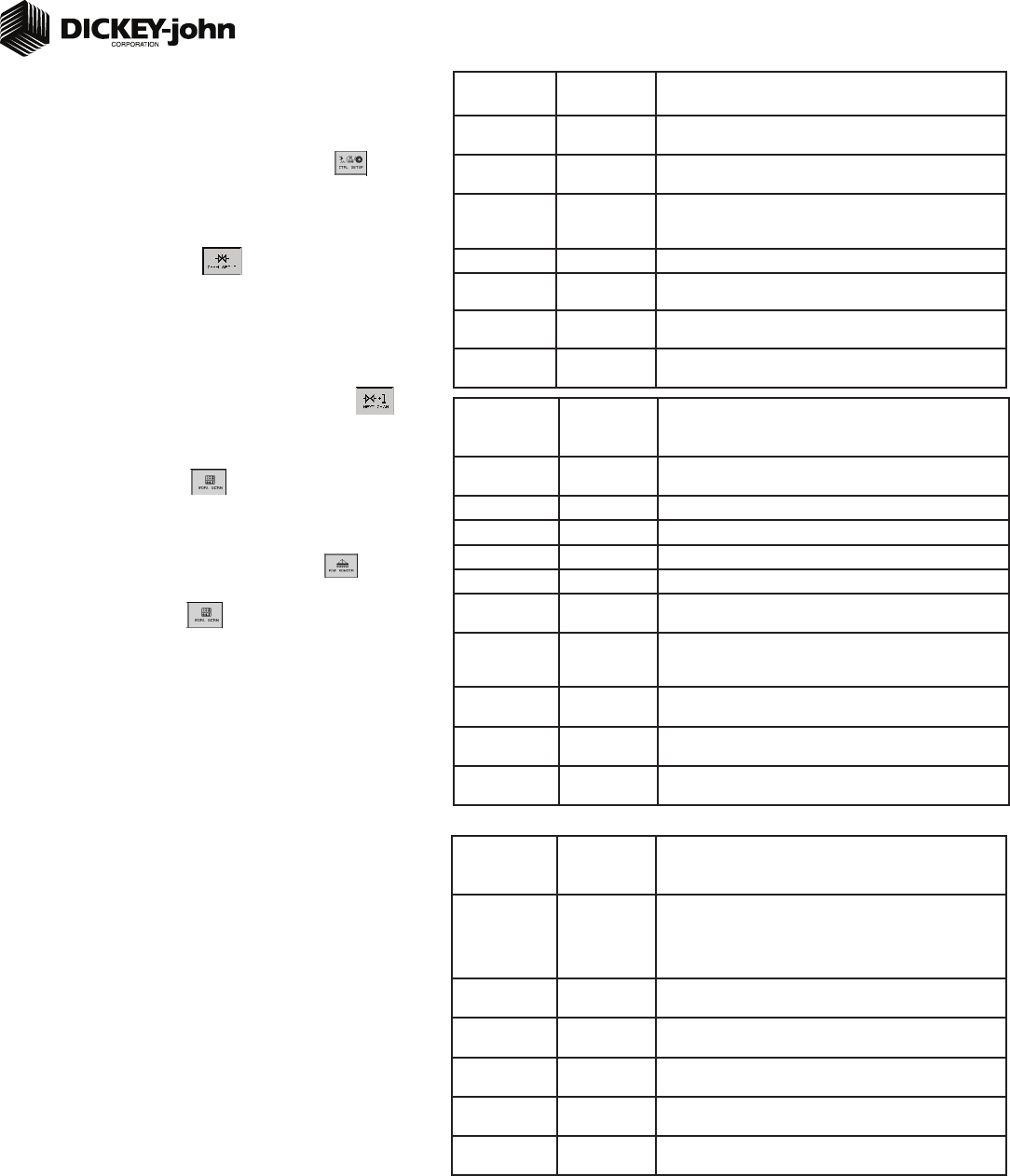
TABLE D2:
Planter Control
Setup
Default Value
or Value to
Enter
Split Air Regulation
Instructions/Defi nitions
Type Split Air
Regulation
Confi gure Control Channel 2 as Split Air Regulation.
Material Name Air Create Material Name as “Air”.
Control Mode Auto Control channel feedback based on air pressure sensor.
Drive Type Air Reg 2 Automatically selects Air Reg 2 as drive type.
Input Filter 79% Amount of fi ltering applied to the control channel feedback frequency.
Pressure Drop 0 Difference in pressure sensor mounting location to the seed disk in
inches of H
2
0.
Pressure Slope 447.2269 The change in pressure sensor voltage to a frequency readable by
the IntelliAg system and measured in inches of H
2
0. Should only be
adjusted by qualifi ed personnel.
Pressure Offset 800 Takes a zero point reading that provides a frequency when the fan is
off. Press the Zero Pressure button to calculate frequency.
Planter Selection YP12 Select Planter Selection of YP12 to automatically adjust to the ap-
propriate calibration settings.
Sensitivity Adjust 0 Increases or decreases the calibration parameters in the ranges of -10
to +10. Increasing response time makes the system respond quicker.
STEP 7B: Planter Control Channel Setup
(Split Air Regulation)
NOTE: Split Air Regulation must be confi gured as Control Channel 2 only.
At the Channel Setup screen, press the Next Channel button .
At Channel 2 screen, select Split Air Regulation as the Type.
Enter desired values from Table D2.
Press the Work Screen button to return to the Main Work screen.
1.
2.
3.
4.
3
STEP 8: Row Monitor Setup
At the Main Work screen, press the Row Monitor button .
Enter desired values using Table E as reference.
Press the Work Screen button to return to the Main Work screen.
1.
2.
3.
TABLE E:
Row Monitor
Setup
Default Value
or Value to
Enter Instructions/Defi nitions
Material Name See Instructions Material Name only appears on the Row Monitor Setup screen when
all control channels are disabled and material is set for Monitor Only.
This is only used for ground drive/nonhydraulic applications to monitor
population with high and low alarms. A material must be confi gured
and selected to activate alarms.
High Alarm Delay 5 Desired number of seconds that high population can be above high
alarm point before alarm will sound.
Low Alarm Delay 5 Desired number of seconds that low population can be below low
alarm point before alarm will sound.
Population Adjust 100 Enter a % to allow for seed sensor population inaccuracies to achieve
the desired population display. 100% represents true calculation.
Population Filter 50 Set fi lter value to stabilize the monitored population display. Number
can be set to 0% for no fi ltering and 99% for high level fi ltering.
Row Fail Rate 2/1 (2 seeds
every 1 second)
Set to desired number of seeds per second to trigger seed sensor
failure alarm.
STEP 7A: Material Confi guration Setup (Split Air Regulation)
It is recommended that when setting a control channel for split air, the
material name be created as “Air” to eliminate confusion between the actual
material and the control used.
At the Main Work screen, press the Control Setup button
.
Press Material button 16 for Split Air Control.
Create Material Name as “Air”.
Enter desired values from Table D1.
Press the Channel Setup button to proceed to the Channel Setup
screen.
1.
2.
3.
4.
5.
TABLE D1:
Material Setup
Default Value/
Value to Enter
Split Air Regulation
Instructions/Defi nitions
Type Split Air Reg Desired type of application control channel being used for a specifi c
material. CREATE MATERIAL NAME AS “AIR”.
Units In H
2
0
Oz in
2
Automatically changes with the type of material application selected.
Changes units for target application.
Preset Method Disabled User-defi ned target rates can be confi gured and when enabled can be
adjusted from the Main Work screen using the Increment/Decrement
buttons.
Target Rate 2.00 Establishes the desired rate of application in inches of H
2
0.
Max Rate 5.00 Maximum application rate in inches of H
2
0.
Min Rate 1.00 Minimum application rate in inches of H
2
0.
Inc/Dec % 5% Percentage of change of the entered target rate applied each time the
Increment/Decrement button is pressed on the Main Work screen.
 (70 pages)
 (44 pages)
 Manymanuals.com
 Manymanuals.de
 Manymanuals.fr
 Manymanuals.it
 Manymanuals.pl
 Manymanuals.cz
 Manymanuals.es
 Manymanuals-pt.com
Commentaires sur ces manuels